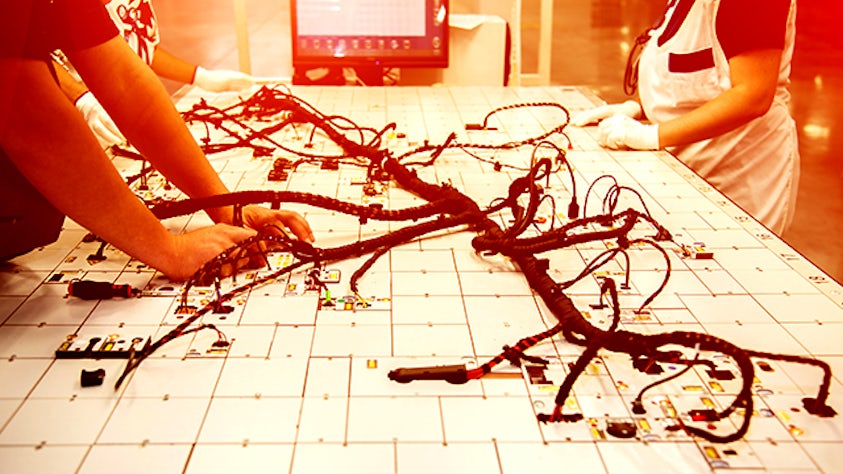
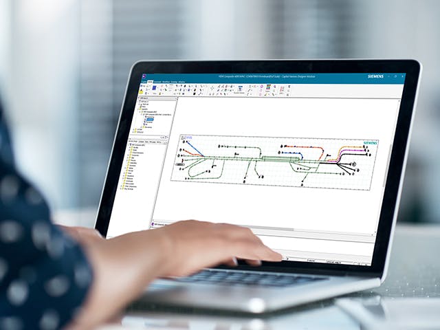
A formboard drawing is synonymous with a formboard diagram. Formboard designers need to create optimized layouts that reduce time and effort related to each component as it is placed in a particular zone on the board. A formboard diagram is a view of the wire harness design data as a digital twin. This diagram is augmented by zonal, fixture and drill point information, and it enables layouts to be created without the need for physical prototypes.
What is wiring harness design?
Wire harness design is the process by which an engineer evaluates the requirements of an electrical part of system, given available physical space to create an assembly of wires to deliver power and information as needed. The design must connect all necessary components and not interfere with other systems critical to the operation and purpose of the product.
Formboard drawings in wire harness manufacturing
Effectively designed wire harness formboards enable manufacturing engineers to build production lines that are more efficient. Formboard drawings enable the creation of efficient production lines that use existing manufacturing resources as effectively as possible while facilitating quick reactions to new situations such as changing Takt times, the required product assembly duration needed to match demand. The results are better shop floor decisions and reduced time to profitability.
Benefits of a merged formboard
Using merged formboards, manufacturing engineers can design production lines which allow them to produce different (but very similar) harnesses on the same line. That is, multiple production lines can be replaced by a single, merged line, freeing up available factory space and other resources. Under some conditions, the productivity and efficiency of individual production lines can be increased by using merged formboards.
Digital twin formboard solution
A comprehensive E/E systems development solution can enable a digital twin approach to creating a formboard. Such software can guide formboard designers to create optimized, ergonomic layouts based on dynamic feedback of labor effort or times related to each component, as it is placed in a particular zone on the board. Designers can also create and maintain merged or combined formboards for efficient production lines and factory space usage.
Comprehensive E/E systems development solution
Capital is an example of a comprehensive E/E systems development solution that can be used for formboard design. It covers the design, manufacture and service of electrical systems as well as encompassing E/E system and software architectures, network communications and embedded software development.
This software enables you to:
- Create a full-scale view of the existing design data in a formboard diagram.
- Adjust the formboard for the best ergonomic layout using live metrics and analysis.
- Easily manipulate bundles to fit the harness to the board, honoring minimum bend radius and other constraints.
- Automatically place fixtures in the correct location using automatic rules and constraints.
- Merge or combine multiple formboards to maximize manufacturing efficiency.

